Tire Fitment Calculator: Wheel & Tire Clearance Comparison
Use this tire fitment calculator to compare complete wheel and tire packages, evaluate lateral position shifts relative to the hub plane, and check suspension and fender clearance.
Package Position Summary
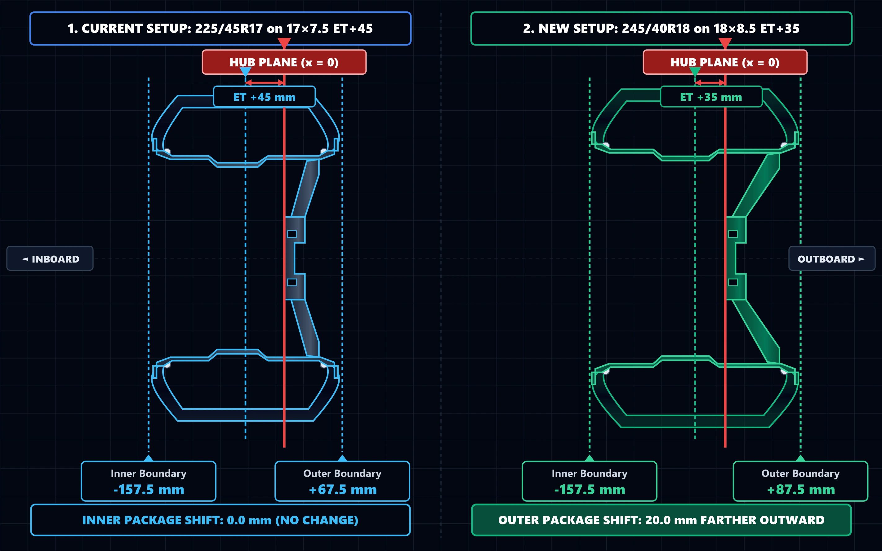
The innermost boundary of the new package sits at the exact same lateral distance from the hub plane.
The outermost package boundary extends 20.0 mm farther outward toward the fender side.
| Boundary | Current Package | New Package |
|---|---|---|
| Inner Limit | -157.5 mm· Tire Sidewall | -157.5 mm· Tire Sidewall |
| Outer Limit | +67.5 mm· Tire Sidewall | +87.5 mm· Tire Sidewall |
Calculations use documented geometric and mathematical relationships, with tire-industry standards and manufacturer specifications referenced where relevant.
How the Tire Fitment Calculator Works
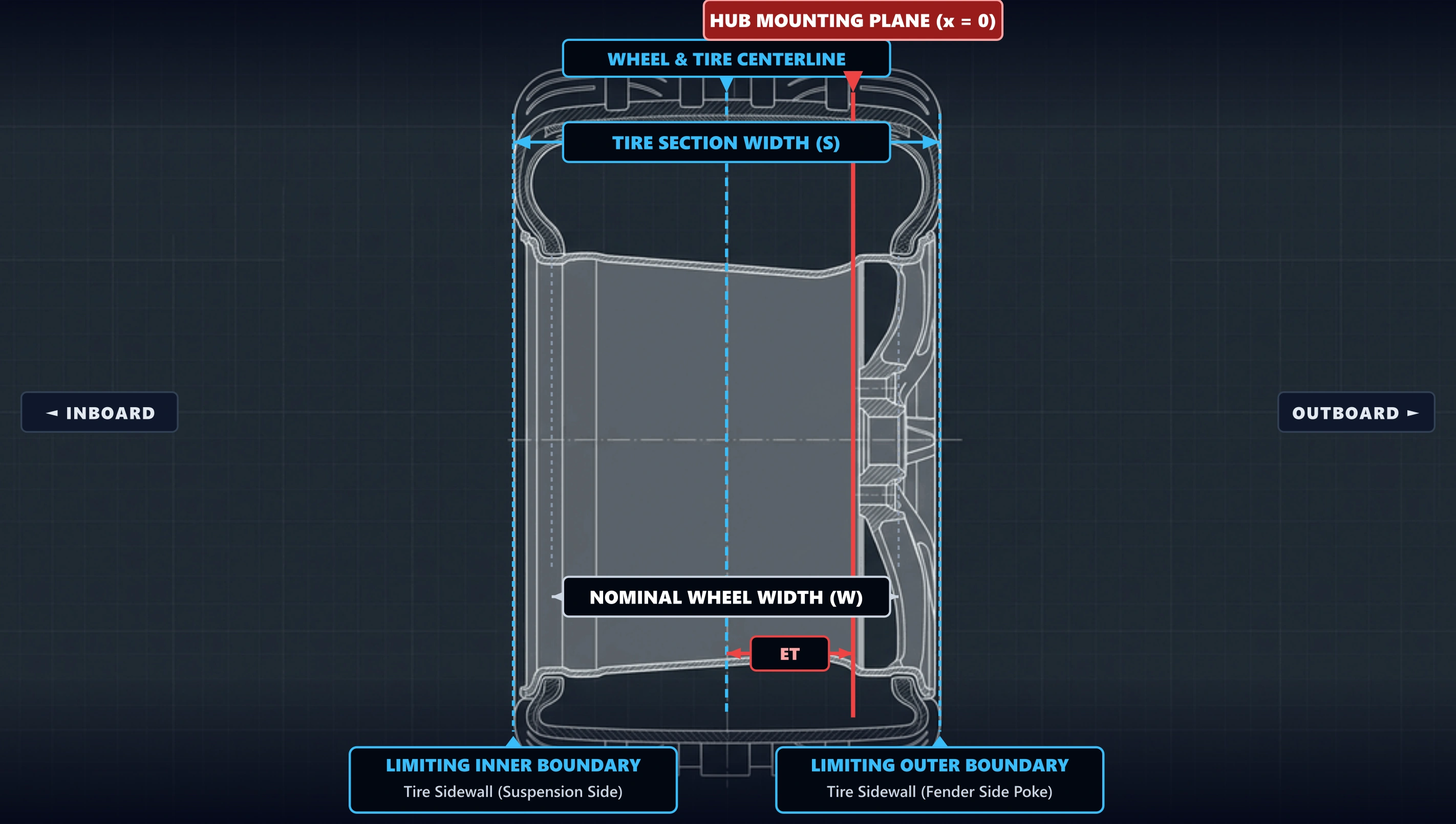
Wheel and tire fitment is determined by the combined lateral envelopes of the tire and wheel relative to the hub mounting plane (x = 0 mm). While wheel-only calculators evaluate bare rim lips, complete vehicle fitment requires analyzing the full package envelope relative to the vehicle hub mounting plane.
- Establish Centerline Position: Calculate the wheel/tire centerline position as x_center = -ET relative to the hub mounting plane.
- Calculate Tire Sidewall Envelope: Determine the inner tire sidewall as -ET - (S / 2) and outer sidewall as -ET + (S / 2), where S is tire section width.
- Calculate Wheel Rim Lip Envelope: Determine the inner wheel lip as -ET - (W_overall / 2) and outer lip as -ET + (W_overall / 2).
- Select Limiting Boundaries: Set the limiting inner boundary as min(Tire_inner, Wheel_inner) and outer boundary as max(Tire_outer, Wheel_outer).
- Derive Package Movement Deltas: Compute inner movement delta (Δ_inward) and outer movement delta (Δ_outward) between setups.
Worked Fitment Examples
• Current Inner: -45 - (225/2) = -157.5 mm
• New Inner: -35 - (245/2) = -157.5 mm
• Δ_inward = -157.5 - (-157.5) = 0.0 mm (No change)
• Current Outer: -45 + 112.5 = +67.5 mm
• New Outer: -35 + 122.5 = +87.5 mm
• Δ_outward = +87.5 - (+67.5) = +20.0 mm (Poke)
The nominal inner package boundary does not move, while the outer package boundary extends 20.0 mm farther outward. Actual suspension and body clearance still depend on vehicle geometry and mounted tire dimensions.
• Current Inner: -25 - (265/2) = -157.5 mm
• New Inner: 0 - (285/2) = -142.5 mm
• Δ_inward = -157.5 - (-142.5) = 15.0 mm farther outward
• Current Outer: -25 + 132.5 = +107.5 mm
• New Outer: 0 + 142.5 = +142.5 mm
• Δ_outward = +142.5 - (+107.5) = +35.0 mm (Poke)
The inner package boundary moves 15.0 mm farther outward, while the outer package boundary extends 35.0 mm farther outward. If the suspension-side reference remains fixed, the static package-to-reference gap would increase by 15.0 mm before accounting for tire deformation or vehicle dynamics.
Popular Plus-Sizing Fitment Scenarios
Comparative package movements calculated from nominal tire designations and standard wheel widths:
| Current Setup | New Setup | Inner Package Shift | Outer Package Shift | Diameter Delta |
|---|---|---|---|---|
| 225/45R17 on 7.5 ET45 | 245/40R18 on 8.5 ET35 | 0.0 mm (No change) | +20.0 mm outward | +3.0% (+18.9 mm) |
| 205/55R16 on 6.5 ET50 | 225/45R17 on 7.5 ET45 | 5.0 mm farther inward | +15.0 mm outward | +0.4% (+2.4 mm) |
| 265/70R17 on 8.0 ET25 | 285/70R17 on 9.0 ET0 | 15.0 mm farther outward | +35.0 mm outward | +3.5% (+28.0 mm) |
| 245/45R19 on 8.5 ET40 | 275/35R20 on 9.5 ET35 | 10.0 mm farther inward | +20.0 mm outward | -0.4% (-2.6 mm) |
*Calculations derived directly from nominal tire dimensions and wheel geometry. Measured mounted widths vary with manufacturer casing geometry and rim contour.
How Measuring Rim Width Affects Tire Section Width
A tire size such as 245/40R18 provides a nominal section-width designation, but manufacturer-published section width is measured on a specified measuring rim. In Advanced Section-Width Mode, the calculator uses the manufacturer's published section width and measuring-rim width to estimate how the lateral section width changes on the installed wheel.
- Nominal vs Published Dimensions: Measuring-rim widths are specified in tire manufacturer and tire/rim technical data, but they are not encoded directly in the tire-size designation.
- Installed Rim Variation Rule: When mounting a tire on an approved wheel wider or narrower than the design measuring rim, Michelin technical specifications support an industry approximation of approximately a 0.2-inch (5.0 mm) section-width change per 0.5-inch change in rim width relative to the measuring rim.
- Strict Lateral Isolation: This adjustment affects lateral package geometry only. It does not alter the calculator's nominal tire diameter, sidewall height, circumference, ride-height change, or speedometer calculation.
How Measured Baseline Clearance Works
Measured Baseline Clearance Mode starts with the shortest current static gap between the existing wheel/tire package and a selected fixed vehicle reference surface, then applies the calculated package-position change to estimate the remaining static gap with the new setup.
Remaining Gap = Current Inner Gap − Δ_inward
Remaining Gap = Current Outer Gap − Δ_outward
A positive movement delta reduces the remaining static gap, while a negative movement delta moves the package away from the reference and increases the remaining gap.
- Measurement Conditions: Gaps must be measured on the same axle and location, at normal static curb ride height, with steering centered, and to the same fixed suspension or bodywork surface.
- Scope Limitation: Static gap estimates do not account for dynamic suspension compression, steering lock sweep, tire carcass deflection under load, or body roll. Physical fitment verification on the vehicle is always necessary.
Mathematical Formulas & Geometric Derivations
Wheel terminology follows SAE J1982 nomenclature. The fitment engine applies a one-dimensional coordinate model to calculate tire, wheel, and package boundaries relative to the hub mounting plane:
1. Dual Component Lateral Envelopes
Tire Inner: x_t,inner = -ET - (S / 2)
Tire Outer: x_t,outer = -ET + (S / 2)
Wheel Inner: x_w,inner = -ET - (W_overall / 2)
Wheel Outer: x_w,outer = -ET + (W_overall / 2)
2. Package Movement Deltas
Inner Shift: Δ_inward = Inner_curr - Inner_new
Outer Shift: Δ_outward = Outer_new - Outer_curr
Δ_inward > 0 = package boundary extends farther inboard / suspension side.
Δ_outward > 0 = package boundary extends farther outboard / fender side.
Understanding Package Boundaries (Figure 1)
The modeled package boundary is the outermost lateral envelope produced by the tire-sidewall boundary and wheel-lip boundary:
Wheel + Tire Package Cross-Section Anatomy
Lateral Shift Mechanics (Figure 2)
When changing both tire size and wheel offset simultaneously, the combined package movement shifts relative to the fixed hub mounting plane:
How Tire Width & Wheel Offset Shift the Package
Real-World Vehicle Fitment Constraints & Limitations
Geometric package calculations establish theoretical position shifts, but complete vehicle fitment is governed by dynamic mechanical factors:
- Brake Caliper Clearance (X-Factor): Spoke curvature, barrel drop-center geometry, and brake caliper dimensions cannot be determined from wheel offset or tire size alone.
- Suspension Articulation & Compression: Bump travel compresses the wheel into the wheel well, where camber curves alter top-of-tire clearance.
- Full Steering Lock Sweep: Turning the steering wheel sweeps the tire shoulder through an arc, creating clearance pinch points at the front bumper liner and firewall.
- Dynamic Tire Carcass Deflection: Tire sidewalls deflect laterally under hard cornering and vertically under vehicle payload.
- Standardized Approved Rim Contours: The Tire and Rim Association Engineering Year Book publishes tire and rim dimensional information, including approved rim contours and rim contour dimensions for tire sizes.
Related Tire & Wheel Calculators
Need isolated tire diameter comparisons, single-tire unit conversions, or bare wheel offset calculations?
Frequently Asked Questions
References
- SAE International – SAE J1982_202303: Nomenclature - Wheels for Passenger Cars, Light Trucks, and Multipurpose Vehicles. Standardized engineering nomenclature and definitions for wheel offset, mounting face, and centerline.
- The Tire and Rim Association Engineering Year Book. Standardized tire and rim dimensional information, including tire dimensions, approved rim contours, and rim contour dimensions.
- Michelin Technical Specifications. Tire dimensions are reported using specified measuring-rim widths, with section width varying approximately 0.2 inch (5 mm) for each 0.5-inch change in rim width.